This article will cover isolation and the correct use of Henley blocks in an installation.
Where Henley blocks are used in domestic premises to supply an additional consumer unit for say, an electric shower circuit, questions sometimes arise about how to comply with Regulation 537.1.4 which requires a main linked switch or a linked circuit-breaker at the origin of each installation.
A typical question would be – do I need to fit a main isolating switch between the meter and the Henley blocks to isolate the main consumer unit and the additional consumer unit simultaneously?
Requirements of BS 7671
Two regulations in BS 7671 are particularly significant:
- Regulation 537.1.3 states, ‘Each installation shall have provision for disconnection from the supply’ and
- Regulation 537.1.4 requires that, ‘A main linked switch or linked circuit-breaker shall be provided as near as practicable to the origin of every installation as a means of switching the supply on load and as a means of isolation’.
The references to, ‘Each installation’ and, ‘every installation’ in these regulations means we must clarify what exactly is meant by an electrical installation. For example, is the additional consumer unit and the circuit(s) supplied by it, part of the main installation or is it counted as a second installation?
Another point which requires explanation is whether or not the double-pole main switches in both consumer units comply with the requirements for switching and isolation in Section 537 of BS 7671.
What is an electrical installation?
An electrical installation (which can be abbreviated to ‘installation’) is defined in Part 2, Definitions of BS 7671 as follows:
‘An assembly of associated electrical equipment having co-ordinated characteristics to fulfil specific purposes’.
By this definition, an electrical installation can be considered to include a domestic consumer unit and the final circuits supplied by it.
Likewise, an additional consumer unit provided for a specific purpose, such as supplying an electric shower, or Economy 7, can also be considered to be an electrical installation.
Therefore, premises, including domestic premises, can have more than one electrical installation but each installation must have its own means of disconnection from the supply which must be located as near as practicable to the origin of the installation.
In such situations, Regulation 537.2.2.6 requires that each isolating device must be clearly identified by position or by durable marking to indicate the installation or circuit it isolates.
Key question
Does the double-pole main switch in a domestic consumer unit comply with the requirements for switching and isolation in Section 537?
Domestic consumer units comply with BS EN 61439-3 but the main switches within them generally comply with BS EN 60947-3 which is a requirement of Section 537 (see Table 53.4).
Consequently, in domestic installations, it is not necessary in principle to install a separate isolator upstream of the consumer units – before the Henley blocks – in order to isolate both consumer units simultaneously.
However, an isolator may be still be required as explained in the paragraph on isolation of meter tails at the origin.
Overload and fault current protection of meter tails
Protection of meter tails against overload and fault current may be omitted provided the distributor agrees that the protection given by the cut-out fuse is suitable. A condition of this agreement may be a restriction on the length of the meter tails.
Isolation of meter tails at the origin
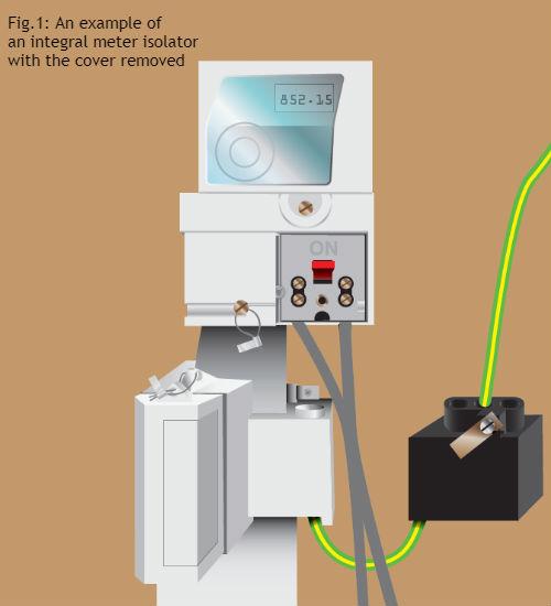
Regulation 537.1.3 states that, where the distributor provides a means of disconnection at the origin of the installation, it may be used, subject to the agreement of the distributor, as the means of isolation for the part of the installation between the origin and the main linked switch or circuit-breaker required by Regulation 537.1.4. This isolator can take the form of an integral switch within the meter (Fig. 1).
The distributor will usually require that a means of isolation is installed if the meter tails exceed a certain length. Distributors often stipulate different maximum lengths for meter tails but a maximum length of 3 metres is common.
A fused switch is recommended over 3 m by the Distribution Connection and Use of System Agreement (DCUSA).
The Note to Regulation 537.1.3 draws our attention to the fact that a cut-out fuse cannot be used for isolation by persons who are not authorized to do so by the distributor.
Regardless of whether or not it is required by BS 7671, there can be little doubt that the provision of an isolator at the origin of an installation is good practice. Where a contractor has called out the distributor to withdraw the cut-out fuse, a convenient opportunity is presented for an isolator to be fitted at the origin of the installation. This could be carried out either by the distributor or by the contractor. Thereafter, it would no longer be necessary to call out the distributor to withdraw the cut-out fuse.
A suitable layout
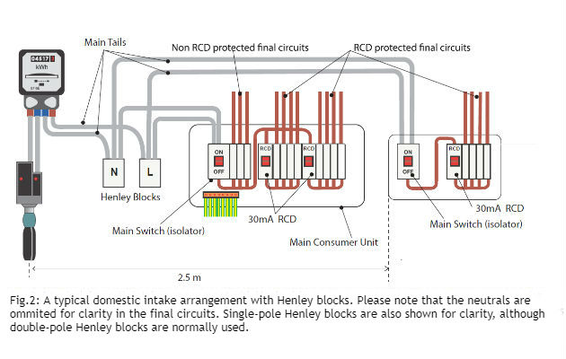
Fig. 2 shows a suitable layout for the domestic arrangement involving Henley blocks.
More than one source of supply
Where an installation is supplied from more than one source, such as where an additional source of supply is provided by, for example, a PV installation, the situation is somewhat different.
Regulation 537.1.6 requires that a main switch be provided for each source of supply. In addition, a durable warning notice must be permanently fixed in a position such that any person seeking to operate any main switch will be warned of the need to operate other main switches in order to isolate the whole installation.
Alternatively, a suitable interlock system must be provided such that the main switches can be operated simultaneously to disconnect each source of supply.
Regulation 537.1.5 deals with a situation where one source of supply requires a means of earthing which is independent of the means of earthing of the other supply sources.
Further reading
IET Guidance Note 2, Isolation and Switching.
Electrical Safety First Best Practice Guide 2, Guidance on the management of electrical safety and safe isolation procedures for low voltage installations.
Source: https://www.voltimum.co.uk/articles/technical-guide-henley-blocks-and